
A Logical Approach to CAD Data Exchange
Data Exchange and the Supply Chain
CAD data exchange is the term usually applied to the movement of 3D design data between collaborating design/engineering/manufacturing companies. It can be considered like this; if the hierarchy of CAD data exchange is a triangle with an OEM at the top, Tier 1 suppliers at the next layer, sub contractors for the top tier suppliers below that, the flow of CAD DATA Exchange can be viewed as a bi-directional stream flowing from the top to the bottom and vice versa.
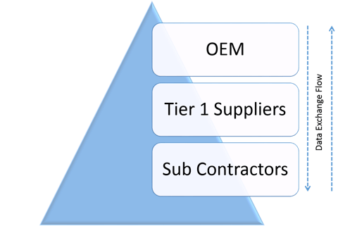
However, although the data flow can be described as a bi-directional stream, the content of the data changes. The data that moves between OEM and top tier supplier is not normally the same as that which moves between top tier supplier and the subcontractors below. Typically, the data that goes between OEM and top tier supplier is very large in size and complex. It could be native CAD data, it could be STEP or it could be a visualisation format such as JT.
The engineering at the bottom end of the supply chain includes things like tool design and manufacture, tool holding design and manufacture, and the design and manufacture of smaller components that are integral to the component that is created at top tier supplier level. These items are important because they are often on the delivery time critical path and the optimisation of CAD data exchange processes at this level is highly desirable.
More and more different types of CAD data forces CAD Data Exchange
As if the complexities of CAD data exchange between collaborating companies were not a sufficient challenge to the design/manufacturing industries, there is often a significant internal overhead. Increasingly companies, especially those in the automotive and aerospace supply chains, have more than one CAD system. Having two active systems is quite common and it is not unusual to find three. At the time of writing these are normally CATIA, NX and Creo but it is also possible that CADDS is still in place and even if not active as a design system, a large legacy of CADDS data may still be present.
It could be argued that the presence of two or three different types of CAD system enables interoperability with more customers without the need to translate data, but it simply moves the point at which the CAD data translation takes place. A project can easily overflow the resources that are available and if the resource is a CAD system it makes sense to overflow from one CAD system to another.
CAD data exchange or interoperability or whatever it gets called next, is not a straightforward process. This is an attempt to help people highlight, and then side-step, common problems that may occur during their data exchange lifecycle. It isn’t intended to be the definitive guide to data exchange, but some hints and tips built up from practical experience and knowledge of the data exchange field.
Know what you expect to receive and check it when you get it
If you’re going to have to import or translate ‘foreign’ data it helps if you know what you are going to receive. It gives you the chance to plan, and to ensure that when it does arrive you’ve got enough time, and the appropriate translation tools for the job.
Can you view it? Can you see if it is an assembly rather than a single part? Does it contain colours and other attribute data you might need? How large are the files? Have you worked with data from this person and this source before? Does it look like business as usual or is this something new?
Treat incoming data with care
Almost all data that is sent between companies for collaborative work contains intellectual property of one, or both, companies. Such data should be treated with care. Electronic files should be stored in secure areas and not left attached to a memo in an email in-box or in a directory on a public FTP site. Ideally there should be a process that receives the data-and before any validation, records what has arrived, puts the data in a secure place, and tells the sender that it has been safely received. A similar process should be in place for data that is received on physical media such as a USB drive or DVD. It should not be left in its envelope lying about on a desk it should be placed in a secure media store.

Only translate what you need
It is not unusual to receive more data than is needed for the job. An extreme example might be a manufacturer of hinges receiving half a car body in order to ensure correct placement and fit of door hinges! It’s not always as bad as that, but it happens. The ideal situation would have been to have had sufficient dialogue with the sending organisation beforehand to agree exactly what data is needed and to send just that.
However, sometimes that can’t happen. One problem this can create is just how to handle very large files. Receiving a big CAD file that is not directly compatible with your own CAD system is not good. How big is big? CAD files of fifty or a hundred megabytes are not infrequently found, and IGES or STEP files can sometimes be gigabytes in size! It’s a fact that the bigger the file the more likelihood there is of a translation failure – the machine you are doing the translation on may run out of memory. It is rare to need to work with that volume of data, and if sending files that big can be avoided, it helps.
If you find yourself on the receiving end of such a file there are several things you can do. You could ask the sender to provide you with an assembly as a set of sub-assemblies - but this might be commercially sensitive and pass negative signs to the sender, and so may not be practical. The sender may simply not be able to disassemble the file or remove parts of the file to make things easier for you. Perhaps this is the last resort.
If you are very familiar with the translation tool you are using you may find that you can translate just the geometry that you need. It may be, for example, that a layering convention has been used and you can translate the layers that you want- or exclude the layers you don’t. It may be that the geometry that you want is surface geometry, so your solution might be to translate just the surfaces. In short, knowing the capabilities of your translation tools can help you manage large files, save time and help get the job done.
How do you know if you've succeeded?
In data exchange, if the translator only gives limited warnings and it produces a file we generally assume success. It can be dangerous to make this assumption. At this stage all that can be known for sure is that a file has been created and perhaps can be read into the target CAD system. It is not possible to say from what has happened so far that it has produced an equivalent CAD model to the original. There are different ways to validate files and they all have their strengths and weaknesses. We might have a perfectly sound model but it may not be the same as the original. We could ask the sender for mass property details of the original and make some comparisons but even if they appear the same, the shape could be different. Sometimes visual inspection of the source model, and just making a visual comparison with the destination model is sufficient to see a problem, however not seeing a difference does not mean that one doesn’t exist. Validation is a difficult area.

Fortunately, we have now reached the stage where most translators work most of the time and one way or another we seem to be able to exchange data without having too many problems of this sort- especially where we are just exchanging a few files every now and then. The true size of this problem is not clear.
The necessity for validation varies depending on the intended use of the translated data. The question of accuracy and completeness of a translation becomes very important where complex shapes are used to create expensive tooling, or when we have dozens of files, most of which we will not check visually. It is even more of an issue in migration projects where tens of thousands of files may be translated and are required for future use, not simply for archive purposes. Manual checking would be prohibitively expensive, in terms of both time and money, and so automated procedures need to be in place. Fortunately, there are solutions, and while this post is not a suitable place to describe them, Theorem can provide technical and ‘use case’ detail for those who would like to enquire directly.
What to do when a translation fails
Unless the error message generated during the failure gives a definitive explanation of the problem, you will probably have to try several things.
Perhaps the first thing to do is to put a test file through the translator. If a file known to be good goes through without failing, this will indicate the problem as being in the source file. If, on the other hand, a file that is known to normally translate successfully fails then there are probably issues with the translator. Maybe a licensing issue, or a permissions issue, or perhaps some paths have changed. These kinds of problem are normally solved with a little time and effort.
If the test file goes through the translator with no problems, then the challenge is with the incoming file. Your first decision is whether you are going to try to resolve this yourself or if you are going to pass it back to the person who sent it, or even seek help from your translator supplier.
Assuming that you decide to resolve the issue yourself, here’s where you might start.
If you have a tool which will display the source data, use it to see if the source file looks wholesome. Gaps between surfaces, or missing surfaces may be obvious and could be an indicator that you have a bad file.
Check the file size and ask the person who sent it to confirm what it should be. The process of copying it in the first instance may have caused a problem.
If you understand the log files created by your translator, examining these will provide some clues. Seeing just what the translator was doing when it failed can sometimes point out a problem in the source file that could be avoided by selectively translating layers or entity types. In actual practice the people who can read and understand translator log files are a rare breed and you would be forgiven if you didn’t even want to step into this realm.
Another option is to try to translate the file into a different format. If you have more than one translator you may find that a troublesome file will go into a different format without a problem. That only helps of course if you can then translate that file into your desired format, and of course nobody knows what might have got lost in the course of more than one translation. However, sometimes it works.
Your translator company will normally have tools to investigate the source file and so should be able to tell you if that is the reason for the problem.
Another option is to contact the support centre of your translator supplier; you have paid maintenance haven’t you? The only thing that should now prevent you from creating a file in the format you want is if there is a fault in the source file, and if that is the case you have little option other than to go back to the person who sent the file in the first place.
Send only high quality data
If you want your business partners to successfully import the files you send them make sure you send the best quality files that you can. Run them through whatever ‘checking’ routine there is in your design software. If there are errors – even if they don’t make any difference in your own CAD package, they might be showstoppers in translation. For example, if your CAD package creates solids, even if there are gaps in the surfaces, there is no guarantee that a translated part will be read into another package and represent the data as solid. If solids are important, send solids, not surfaces with gaps.
This kind of problem has given rise to some translators that will ‘fix’ problems like this, but there are several potential issues with this approach. For example, if the fix requires a change of shape does it constitute a design change and if it does should it be allowed to happen? The very best interoperability works with high quality source files and then the issue of design changes doesn’t arise.